The contractors' locomotive
is a very important item of the plant for many engineering works,
quarries, brick yards, etc., and while fineness of finish and economy in
operation are not important requirements, strength of parts and
attachments is exceedingly important to enable the engine to work
regularly over a very rough track and to withstand the shocks and rough
handling to which it is inevitably subjected.
In a majority of cases the engines used by contractors are ordinary
locomotives of small size, with piston rod connected directly to the
driving wheels by a connecting rod, but in recent years geared
locomotives have shown such advantages as to come into favor. We show
herewith a geared locomotive designed for contractors' use, and built by
the John F. Byers Machine Co., of Ravenna, O.
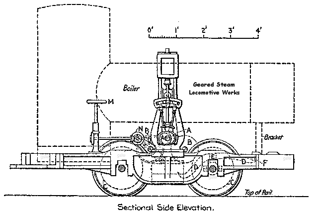
side elevation
This locomotive is a four-wheel tank
engine, and has heavy cast-iron sectional frames, in which are formed
the guides for the axle boxes, and which serve to add to the adhesion
weight of the engine. The wheels are 24 ins. In diameter, and are placed
inside the frame for a track of 36 ins. gage, and outside for standard
gage. They are of cast iron, with chilled treads. Upon the middle of
each side frame is mounted a vertical inverted engine, driving a main
shaft, which carries a driving pinion, A. This pinion
drives two gear wheels B, B, on
countershafts, which in turn drive the two pinions C, C,
on the axles of the carrying wheels. It is plain spur gearing, back
geared 3 to 1, three revolutions of the engine giving one revolution to
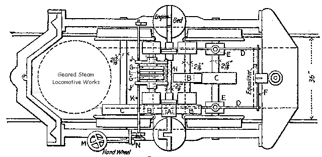
the axles. The gear wheels are cast with solid webs and wide faces, and
the pitch of the teeth is 1 ½ ins. The countershafts are 2 7/16
ins.
diameter, carried in bearings on a transverse frame or bedplate, which
is bolted to the side frames. The main axles are of steel, 2 15/16
ins.
diameter, with large bearings carried in oil boxes. The leading axle has
side-bearing bars D, D, which rest on
bearing boxes on the axle E, E, and these
bars carry the transverse equalizer F. This arrangement
allows sufficient vertical play in the leading main bearings, and also
effects such a distribution of the weight that the engine will ride
steadily over any ordinary inequalities in the track, and will pass
easily around curves of 25 and 30 ft. radius.
The boiler is of T shape, with a circular
firebox in the vertical leg and tubes in the horizontal barrel. This
barrel is entirely filled with water, the water level reaching up into
the vertical leg, and steam is taken from the upper part of this leg,
which serves as the steam dome. The shell is lagged and jacketed in the
usual way. The exhaust pipes run full size to the exhaust nozzle in the
smokebox, and discharge into a petticoat pipe of the usual pattern. The
vertical extension of the exhaust pipes downward on the outside of the
smokebox, as shown in the general view, is for the purpose of a drip,
and the lower end of each extension is provided with an opening 1/8
in. diameter, which is left permanently open. In the later engines the
exhaust is run from the cylinders directly underneath the boiler, and
thence by a single pipe to the smokebox, a single drip pipe with
permanent opening being provided. The sandbox and bell are mounted on
the boiler barrel, and the fittings include a glass water gage, water
try cocks, two injectors, etc.
top elevation
The engine is provided with a friction brake, shown in the side
elevation, which is placed on the rear countershaft. It consists of two
cupshaped disks G, G, faced with wooden
friction blocks H, H. These disks are
attached to two yokes J,
J , which in turn are moved
in line with the countershaft by means of the threads on the operating
shaft K. The brake is applied by moving the disks G,
G against the center disk L, which is keyed
to the countershaft. The yokes J, J and
disks G, G work loose on the shaft, but are
fastened at the lower or forward end of the yokes J, J
to the transverse bedplate. This brake is operated by a horizontal hand
wheel M, and bevel gear N. It is powerful
and sensitive and very easily handled.
The drawings show only the iron frames,
the wooden footboard and front end supports being omitted. The front and
back cross frames have been changed somewhat from the form shown in the
photograph, but the arrangement of the engines, main shaft,
countershafts, gears, driving wheels, etc., is the same in all the
machines. These locomotives are said to give a steady drawbar pull, and
to be capable of hauling a train load of 250 tons (including weight of
cars) at a speed of six to eight miles per hour on a straight and level
track. Their short wheelbase enables them to pass the very sharp curves
usually to be found on contractors' track and industrial railways. Four
of these locomotives have been built thus far, and three of them are in
service, being used by tile Casparis Stone Co., of Logansport, Ind.; the
Buffalo Cement Co., of Buffalo, N. Y., and W. J. Murray, contractor, of
New York city.
|