Four boiler styles or models were manufactured. They are listed below
in the order in which they were manufactured, with the Vertical being the first
type.
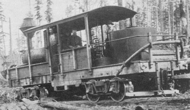
As the name implies, these boilers stood upright. These were very similar
if not identical to the vertical boilers used on steam "donkey" engines used in
the logging industry at the time. Although I have no proof, I would venture a guess these
boilers were selected because they were available and proven to work.
They were of a straight cylinder type with a taper at the top end where the smoke stack
exited. The bottom of the boiler rested on the flooring or special reinforced framing just
below the floor level of the locomotive frame. The firebox was slightly above the bottom
of the unit and positioned facing the fuel storage bin or box, so it could be fired in
practical manner.
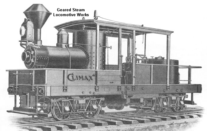
These were used exclusively in the earlier Class "A" units whose frame
resembled a flatcar. As noted below, some Class "A' units were built using the
"tee" boiler. This boiler style was phased out sometime between
1895-96. With the replacement being the "tee" style.
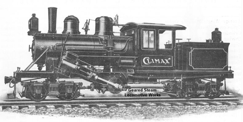
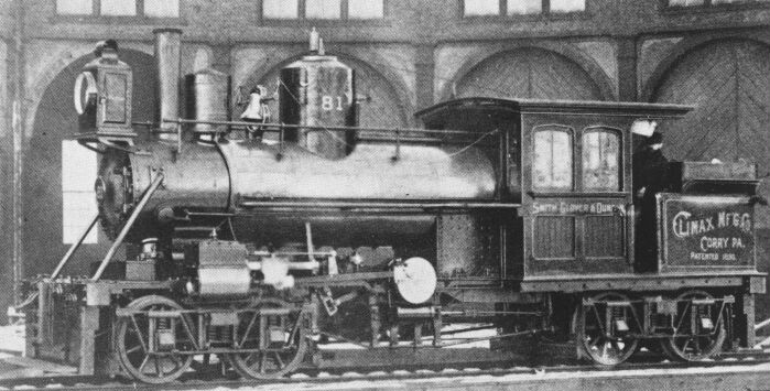
The "tee" boilers resembled a capital letter
T
laying on its side. The horizontal portion or "leg" of the boiler
extended horizontally to the front end of the locomotive frame with the smoke stack
exiting vertically from the front portion of this end of the boiler. The top part of the
"tee", or the vertical portion of the boiler was located in or near the center
section of the locomotive frame. The bottom part of this section extended below the floor
level of the locomotive frame. The firebox was located in this part of the "tee"
and above floor level. A sand dome was placed on top of the horizontal "leg" of
the boiler between the smoke stack and the "tee" part of the unit.
Note in the image above how large in diameter the vertical or "tee"
top portion is and how it high it rises from the where it joins to the horizontal portion
of the boiler. The lower part extends just as far down below the base of this connection.
These were typically used in the Class "A" units. It is with this boiler
style that the Climax began to somewhat resemble a conventional steam locomotive. As
mentioned above, this style was phased in sometime between 1895-96. This change also
required the lengthening of the locomotive frame and added more weight to the entire
superstructure.
The straight was a straight cylinder or tube type boiler mounted in a horizontal
position along the front part of the locomotive frame. Like the
"tee" boiler, the smoke stack was mounted toward the front end of the boiler.
The wagon-top started out at the front of the locomotive as a straight type boiler.
Then, proceeding back toward the cab, at some point it started a gradual flare or
taper outwards a few degrees. This taper continued into the cab, which was modified
somewhat to accomodate the enlarged boiler. The primary advantage of this style of
boiler over the straight boiler was it kept more water over the boiler's
"crown sheet" on grades. Where as any attempt at enlarging
The concave shaped metal wheels had flanges on both the outside and inside of the wheel
itself. They were used on temporary logging "rail" roads where the rail
consisted of two rows of full length tree logs (with the limbs removed) laid end to
end for the entire lengh of the railroad. The concave wheels
"straddled" and thus rode atop the logs, following the direction in which they
were laid.
The metal cleated wheels were designed for temporary logging "rail" roads
where the "rail" was long square lengths of wood positioned end to end and
usually nailed to a stable surface such as logs laid end to end.
The flanged wheels were the type most often associated with locomotive wheels or
drivers. They were metal wheels with a flange or lip an inch or more deep that
ran along the inside (toward the axle) of the wheel. They were used on the
metal rails most commonly associated with railroads. The flange forced
the wheel to follow the curvature or straightness of the track while also preventing the
wheel from "riding" up and jumping over the top of the rail. These
were by far the most commonly ordered and used type of driving wheel for these
locomotives.
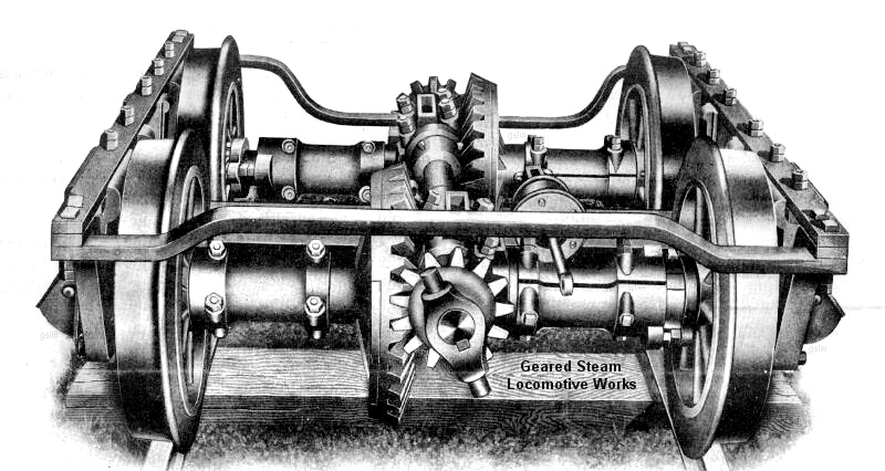
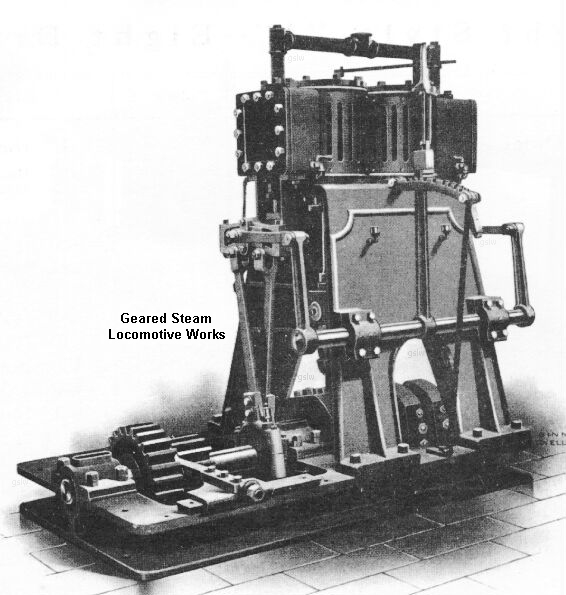
This arrangement was used exclusively in the Class
- Agroup of locomotives manufactured. In this arrangement both cylinders
were positioned vertically and located near the the center of the crew cab, between the
boiler at front and the water tank at rear. Unlike the other two arrangements, the two
cylinders were physically side by side.
This arrangement was first cylinder arrangement manufactured by Climax.
The vertical arrangement was also shared by the Shay and Dunkirk (Class - A) geared
steam locomotives. The Dunkirk - Class "A" cylinders were almost identical in
their cab location to that of the Climax. The cylinders of the Shay, however, were located
together but on the right side of the boiler.
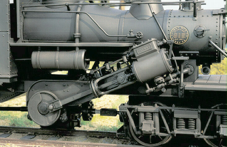
In this arrangement, both were positioned horizontally, with one on either side and just
below the front part of the boiler. The actual location was just above the center of the
front truck and just below the boiler.
This arrangement was the 2nd cylinder arrangement manufactured by Climax. This stage of
design and manufacture was the beginning of the Class - B group. The later and most
prevalent units of the "B" class had the inclined cylinder arrangement.
This arrangement was probably the least prevalent produced by the company with total
production being estimated at less than 5.
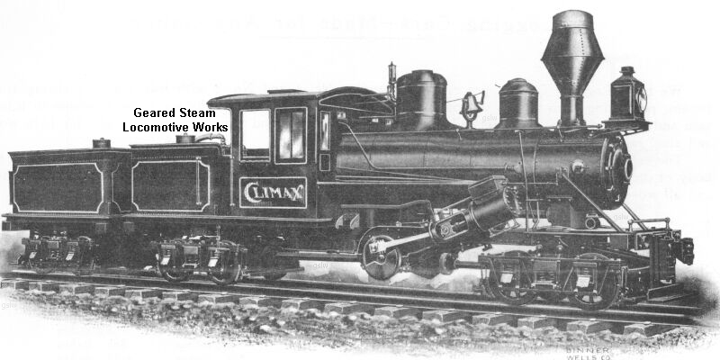
The inclined arrangement positioned the cylinders at an inclined angle from horizontal.
In this position, they were still located, one on either side of the boiler, but were
moved back from the center of the front truck and well above it's rear-most wheel set,
straddling the boiler.
This arrangement was used on the largest quantity of Class - B units and on all Class - C units produced.