|
|
Davenport Fixed Frame Components |
Geared Steam Locomotive Works ©
¬ back || Davenport Main
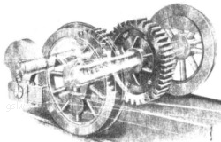
Gearing:
The oil tight and dust proof gear case housed two spur gears which ran in a bath of oil. It was located between and just behind the rear drivers. An excerpt from one of the company's marketing brochures best describes this unique gearing and its perceived advantages:
"The power is
applied through main rods to a crank shaft carrying a pinion which
meshes with and drives a large gear on the rear driving wheel
axle. Power is transmitted to the forward drivers through ordinary side rods, the locomotive thus being driven from all wheels and utilizing for traction the entire weight of the locomotive. Both gears are steel spur gears with extra heavy cut teeth, and a gear ratio of 2 to 1 in an oil-tight gear case, eliminating noise and wear on gear teeth."280dd |
>The first models produced utilized a single speed gearbox. In late 1923, a model utilizing a two speed gearbox was produced. It was hoped the new offering would provide the power advantages of a geared locomotive and allow some increased speed. 240d The two speed gear box offered two speeds forward and two speeds in reverse to the engineer via a power gear shift.
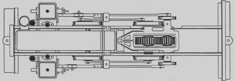
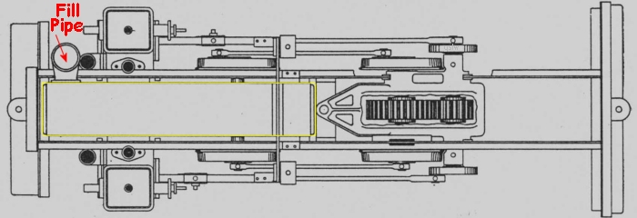
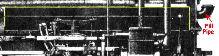
A unique feature on some of the fixed frame models was the water tank. It was mounted
between the frames and below the boiler (outlined in yellow
in photos above). The intent was to
provide a lower center of gravity. For more capacity, additional
side tanks were available as an option. The fill
pipe on these "below boiler" tank models was located either below the
smoke box door (left photo) or on the right side of the locomotive just behind
the pilot beam (right photo). As noted on the Johannesburg Manufacturing #1 locomotive, a more conventional
saddle water tank arrangement was also available.
Page changed: February 21, 2019 04:59:28 PM
