
Crippen's Locomotive 340p
Crippen Geared Locomotive |
Geared Steam Locomotive Works ©
Crippen's Locomotive 340p
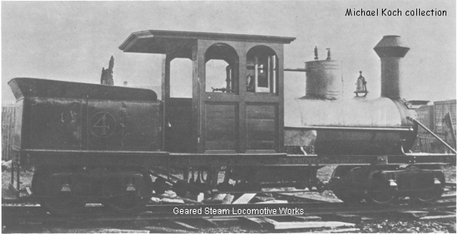
William Crippen and his son operated the William Crippen and Son machine shop and foundry in Clam Lake, Michigan (later part of Cadillac) in the period between 1877 to 1882. Crippen provided design assistance and major hardware components to Ephraim Shay (inventor of the "Shay" geared locomotive) in his early attempts to build a locomotive that was more effective for logging than the "rod type" locomotives of the era. These experiments first produced a chain gear driven, and later, a belt driven swivel truck locomotive that proved somewhat more effective than the "rod type" locomotive for logging. Although Shay abandoned this design in favor of his now famous "lopsided" bevel geared design, Crippen was allowed to copy, build, and sell a few locomotives of the belt driven design to other logging operations in the area. Crippen later went on to patent (on October 17, 1882) and build a single locomotive of his own unique design (pictured above).
Although we do not know the details about the locomotive in the picture above, we get some idea of its "probable" construction and operation by studying the patent drawing and related text. "Probable" is used rather than "actual" because patent drawings and text do not always reflect exactly what gets constructed when a prototype is built. The image above is from the Claude Thomas Stoner collection.
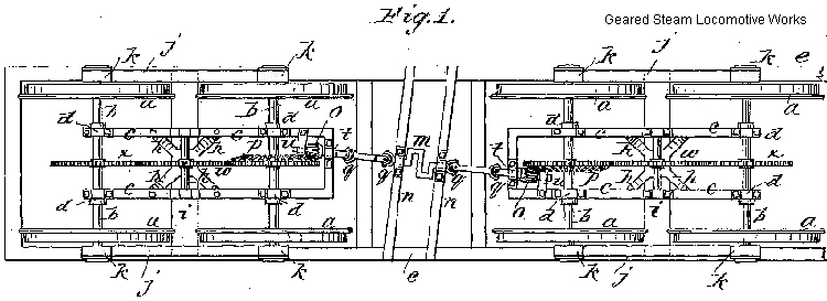
The locomotive's vertical two steam cylinder engine was mounted inside the crew cab. Power was transmitted to the locomotive's two "four wheel" trucks by a crankshaft (m) , universal joints (q), and pinion gears (o) mounted below the cab.
Locomotive-Frame Inverted ViewThe crankshaft appears to have been mounted at an slight angle away from the longitudinal center line of the locomotive-frame. This would lead us to believe the frame of the 2 cylinder engine would have also been positioned at this same angle in the cab.
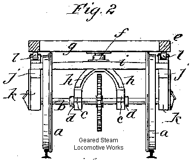
Each truck was mounted to the locomotive frame with a pivot-bolt (f) and bolster (i) that would allow swiveling as curves in the track were encountered. The truck consisted of a frame (c) mounted inside or inbound from the wheels.
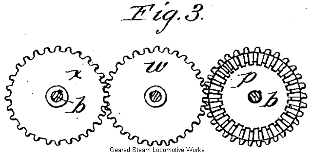
Each truck contained three gears positioned in a line along the longitudinal center of the truck. Two of the gears were of the spur type and the third was a combination "bevel-spur". The "bevel-spur" gear (p) was mounted in the center of the axle of each truck's wheelset that was closest to the middle of the locomotive. The bevel part of this unique gear was driven by the pinion gear (o - Fig. 1). The spur part of the "bevel-spur" gear "meshed" with a spur gear (w) mounted in the center each truck frame. This center spur gear meshed with third spur gear (x) mounted at the center of the out side or end axle of each truck wheelset.
Driving Gear, Side Elevation
Note: The transverse view (Fig. 2) is inaccurate in that it does not show the "face" of the bevel of the "bevel-spur" gear.
References:
- United States Patent #266,103
- "Ephraim Shay, the Man" by Rick Henderson
- "Articulated Steam Locomotives of North America Vol 1" by Robert A. LeMassena
This page changed February 10, 2026 01:32:48 PM